 |
DIY-Welder - Build your own Arc, MIG and TIG welder |
Page hits:  |
Old Boards:
Note: I am no longer building the simplified boards.
I do not have any boards left. So don't ask.
200A Arc, MIG and TIG Welder
 |
 The original, MIG, TIG and Arc (stick) digital board.
Worked well as a test bed.
The original, MIG, TIG and Arc (stick) digital board.
Worked well as a test bed.
|
Update: March 2, 2015 Finally have some progress!
I have been fighting with the options for a new design. The
original digital board was complex and expensive. Some of the
complexities:
- Isolated voltage sense
- Isolated current sense
- Isolated output, up to 200V
- Switching power supply with 3 isolated outputs.
- Lots of analog for real-time control
- 150 parts
- Expensive encoder for input
- MIG, TIG, Stick and battery charger modes.
- Mechanically complex.
- Current sense was hard to calibrate.
It worked, but was never something I wanted to build. Lots
of expensive parts like linear optoisolators. This complexity
was to allow it to be used in 3 configurations:
- DC welder using automotive alternator
- AC/DC TIG and MIG add on for standard engine-driven welders
(I.e a Pipeliner, SA-250)
- Add on for transformer welders like an Airco, Miller DDR/3,
Dialarc and others that use saturation transformers.
The simplified board was just for an alternator. It worked
well but as soon as I started building it, the switches went from
$1.49 to almost $6 each. It was a bit too simplified: it only
drove the field voltage high, was fixed in function and did not
support TIG safely.
Stick (SMAW), TIG and MIG are the goals of the new board. If
all you need is stick welding, the Non-Electronic
Version will be all you need.
One of the problems with the simplified board was no isolation;
everything was referenced to the negative output of the alternator.
DC TIG is electrode negative. So, you connect the positive lead
to the work. That puts the alternator, board and the entire welder
metal at the OCV of the welder, usually 60V. Not a safe situation.
I have been playing with ideas to do this relatively inexpensively.
The first change is to use a modern CPU like a Microchip PIC32.
This will move all the voltage, current and output control from
lots of analog parts to software. That makes it easier to change
and add features like hot start, lift start, engine controls.
Having a built-in display eliminates the need for the user to
add meters or displays.
I have a schematic near done. It is not too bad in complexity
in circuit or mechanically. Still not cheap as I would like, but
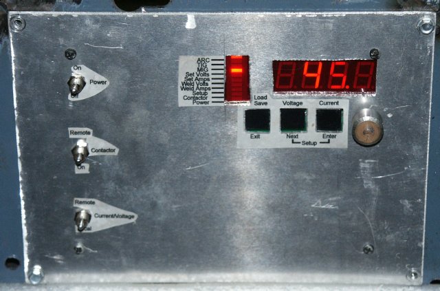
reasonable. The features are so far:
- 4-digit LED display with 10 status LED's.
- User input through 3 toggle switches. Up/Down, Display, and
a mode/remote switch. All switches are 3-position (ON/OFF/ON)
momentary.
- Isolated voltage sense - Allows safer TIG.
- Control output up to 8 amps to support dual alternators.
A build option for up to 200V out (engine welders).
- Stick, TIG, MIG and battery charger modes.
- Current sense via the field current - not real accurate but
good enough. My experience with different welders is the current
setting is approximate any way. 120A on one machine acts differently
than 120A on another.
- PIC32 socketed CPU. Allows for software upgrades. I'd like
to be able to download new code but that adds USB or serial interfaces
that would rarely be used and just adds cost.
- Allow saving and loading configurations.
- Support for an engine idle solenoid.
- Lift start TIG, start at minimum current until arc is established.
- Start power output for an external HF start circuit.
- External Contactor output (useful for better MIG startup.)
- Remote voltage/current control.
- Single board maybe 5x3 inches. This would mount to a 4x6
red plexiglass panel. Would hope to have the panels silkscreened
with all the text and labels.
- Screw terminals for connections.
- Option for external board for true current sense (useful
for engine welders.)
Have some time to develop this now; no definite schedule
though. Not sure on the costs yet. First boards would have to
cover prototype boards, and having the panel made and silkscreened.
If anyone knows a place to have the panels cut, drilled and silkscreened
inexpensively; let me know. Feel free to discuss it on the Yahoo
group at the top of the page.
Schematic so far can be
seen here.
Here is a preliminarey layout. 3.5H x 5W inches
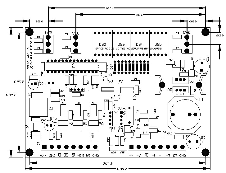 Note: View is from back of board where the displays
and switches are (rest on top side.) So top side parts and text
are mirrored.
Note: View is from back of board where the displays
and switches are (rest on top side.) So top side parts and text
are mirrored.
General info on this site.
You can build a welder with a modified alternator,
a few resistors and some welding cables. Can be powered by a gas
or electric motor. There are several of these floating around
like the "weldernators". They basically work, but have
little output control. They will also likely blow out the rectifier
bridge as there is no protection from the output running away
and no stabilizer for a better arc. These typically run at about
20V; that will work, but hard to maintain an arc.
The idea is to have a generic control board to allow
any power source with current/voltage control to be used for Arc,
MIG and TIG welding. It has a programmable slope and OCV just
like the big welders have. Also it supports both Constant-Voltage
(CV) and Constant-Current (CC) modes so TIG, ARC and MIG can be
done. It can also be used as a fast battery charger.
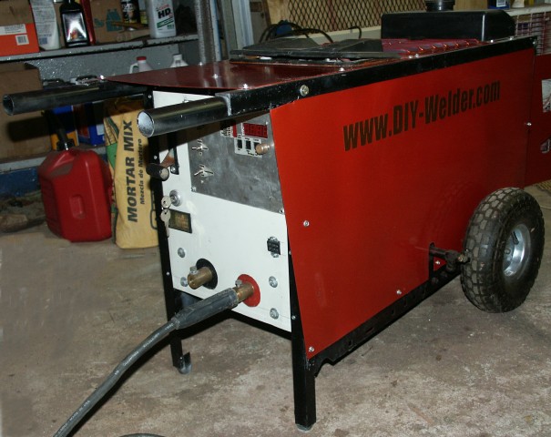
This can be used for a home-built welder that can be
made relatively inexpensively (second prototype shown above.)
The control board with a suitable motor (gas or electric), an
alternator, belt and pulleys and you will have a very capable
DC arc welder. 10HP electric or 12HP gas should be enough for
DIY use. Add gas and a wire feeder and you will have MIG. Add
a TIG torch and gas solenoid and you can do scratch start TIG.
The board has a manual with all the connections explained. Most
of the work is mechanical.
Scratch-start DC TIG is supported. A HF start is planned
The menu at the top shows the options from a simple arc welder
to a multi-process setup. There are also examples of my two prototype
designs..
Questions or comments, feel free to contact me at
All Web pages, images and text Copyright (c) 2009-2015
SHDesigns.