| DIY-Welder - Build your own Arc, MIG and TIG welder | Page hits: |
| DIY-Welder - Build your own Arc, MIG and TIG welder | Page hits: |
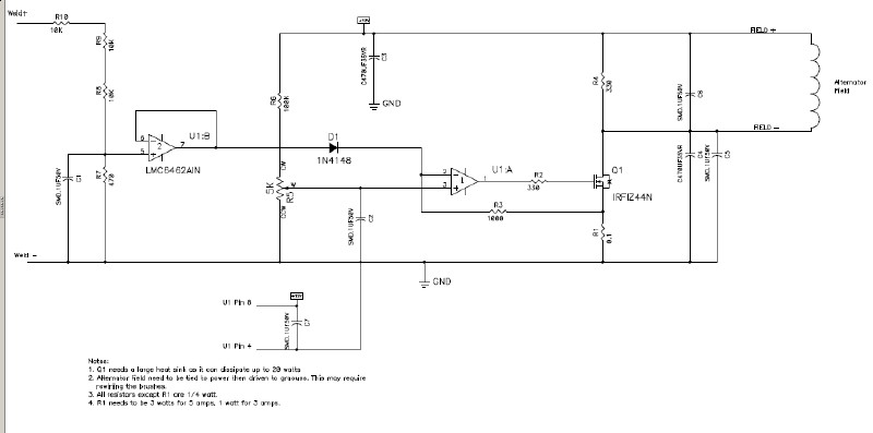
Above is a simple circuit to drive an alternator field with a varying constant current. Click on the image to download/view the PDF drawing
It is easier to drive a signal low; so the field is connected to +12V and then the opposite side is driven low by the circuit.
Q1 needs a large heat sink as it will dissipate a lot of power, probably near 10 watts worse case.
I have not built this yet, it should work but may need some tweaking of the values. There should be a fuse on the +12V power.
Description:
R5 sets a reference voltage of 0 to 0.5 volts. U1A drives the MOSFET Q1 until the voltage measured across R1 matches the reference. That will drive the field with a 0-5 amp current.
The voltage divider on the left feeds U1B. That signal is fed through D1 to the feedback of the current. When the voltage is high enough, it will reduce the output current. this will limit the open-circuit voltage to about 60V.
The three resistors in series on the input prevents arcing across the resistors when you break the arc.
Note, the circuit has the weld - as a reference ground so all signals are referenced from it.