 |
DIY-Welder - Build your own Arc, MIG and TIG welder |
Page hits:  |
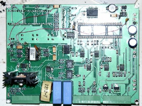
Control board Pictures:
Has a small processor to control the system and display
(empty socket in right picture.) It is software-controlled with
analog circuitry to do the actual current/voltage control. It
uses a PIC processor and custom firmware.
The board has an isolated driver output that can mimic
a rheostat as a remote control for transformer-based arc welders
or control the field of a welder/generator. It can also control
the field of an alternator.
There is also isolated voltage and current inputs.
It has inputs for remote contactor and current control (MIG feeder
or TIG foot pedal) There are contactor and gas solenoid outputs.
Four spare inputs can be used for TIG slope, pulse or gas pre/post
controls. Three 8-pin connectors with screw terminals are provided
for the wiring.
The Two Different Boards:
There will be two boards. The first one shown above was generic
and designed to operate with any power source. This has made it
complicated and expensive to produce
A second board is in development that is simpler. It will basically
have simplified controls and very little digital parts. The features
will be:
- Voltage and current potentiometers.
- External voltage and current displays (has current sense
output.)
- Remote contactor input and switch.
- Remote voltage control and Internal/External switch.
- No save/load option
- External gas solenoid and contactor relay outputs
It should be lower cost and simpler to use. Should be finished
by the early March.
A silkscreened panel will be made also. The idea is to provide
a board users can mount on their welders. It will have the connectors
and wiring diagrams needed.
The second board is coming along, just about ready to have
boards made. The preliminary schematic can be downloaded here.
The schematic shows surface-mount parts. Users who would rather
build their own boards can substitute equivalent thru-hole parts.

