| DIY-Welder - Build your own Arc, MIG and TIG welder | Page hits: |
The first board was digitally controlled but the actual welding current is analog. This allows the board to operate real time without the need for the CPU to process the voltage/current. A block Diagram is shown below:
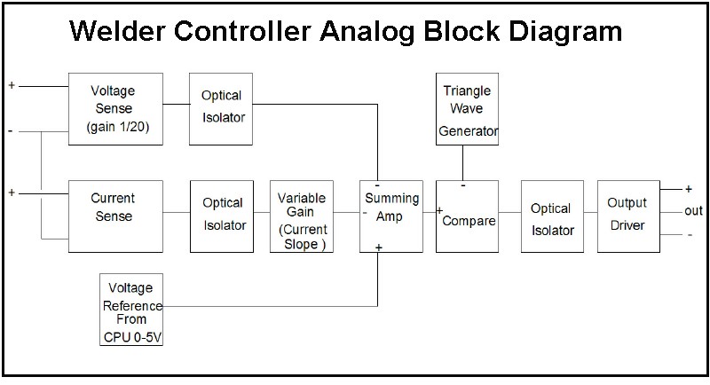
It is basically a switching power supply controller. The CPU generates a 0 to 5 volt reference, that represents a 0-100V welding voltage. The voltage sense amplifier has a gain of 1/20 so a 0-100V weld voltage will output a 0-5V signal. This is fed into a summing amp that generates a difference signal. this difference is fed to the comparator. The comparator is also fed a 20kHz triangle wave. The comparator will then output a PWM signal that varies with the difference in the desired voltage and the actual voltage. This signal is fed to the output driver to control the field current. The output stage uses MOSFETs for efficiency.
For MIG welding, the above is all that is used. For Arc and TIG, the voltage should drop with current. The current sense input will also feed the current into the summing amplifier. A variable gain allows the current slope to be programmable. As an example, suppose the voltage is set to 40V. The current sense is programmed to a slope of 0.3 volts per amp. At about 50 amps, the current sense will output the equivalent of 15 volts. The circuit will then drop the output voltage to 25V. At 100 amps it will drop to 10V.
The inputs and outputs are optically isolated. This is for safety, protection from spikes and also allow the output to drive the field or saturation current off of any power source. There is a small switching power supply that generates 3 isolated power supplies to power the input and output circuitry.
The CPU can program the variable gain via an electronic potentiometer.The voltage reference is generated from a PWM output of the CPU that is fed through a low-pass filter to generate a 0-5V signal. The CPU also monitors the voltage and current sense signals to output to the display.
The "Simplified" board eliminates the isolators so the control circuits are tied to the - output if the alternator. This eliminates a lot of parts. The voltage reference and variable gain are controls on the front panel. It also is designed only to drive an alternator.