| DIY-Welder - Build your own Arc, MIG and TIG welder | Page hits: |
| DIY-Welder - Build your own Arc, MIG and TIG welder | Page hits: |
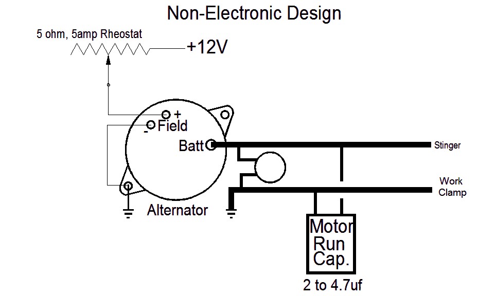
This is similar to the "Weldernator" designs with some improvements for reliability.
The alternator has any regulator removed and the field brush connection brought out externally. The '-' terminal may be left connected to the case if it already is.
A rheostat sets the field current. Depending on the speed and alternator, the values may need to be adjusted. If you can find a 5 to 10-Ohm rheostat that is at least 20 watt or 5 Amp, that will work.
The MOV will suppress the spike when the arc is broken. Without it, the voltage will spike up until the diodes break down. This will reduce the life of them. It should be about 100V. An example can be found on Digikey, search for part # ERZ-V07D101.
The Motor run capacitor also helps reduce surges. These are common on motors and are usually 2.2 to 4.7UF at 300VAC. An electrolytic could be used, but the large voltage changes will reduce the life. The big metal-can motor run caps are much more durable.
The field wires should be #16 gauge wire. The output should be #4 or larger.
+12V is from the starter battery on the engine. It should have a 5 amp fuse.
The rheostat selects the current. Note: when the engine is not running, it should be turned off or it will drain the battery and add wasted heat to the field. A separate switch can be added to the +12V for power on/off.
Set the rheostat near the lowest resistance setting (rightmost position.) Run the engine and measure the output voltage. You would want a no-load voltage of 50 to 70 volts. You may need to adjust the pulley ratio. You don't want more than about 70V or you may damage the alternator diodes.
Try the welder and choose the best rheostat position. you can fine tune the output by adjusting the throttle.
If more output is needed, you can parallel two alternators. Just connect the fields and outputs together. You might try a lower resistance value.
Here is my current setup:

I have an 8-amp thermal breaker on the +12V line (not shown).
For more arc stability, a reactor was added in series with the welder lead. 20 to 30 windings of heavy wire around an iron pipe can make a considerable difference. Mine is 25 windings of #4 wire around a 1.5" ID heavy iron pipe in a steel frame made from 2"x0.125" steel. This smooths the arc amd makes for a bit wetter weld pool.
The 4700uf helps arc starting and maintains a more stable arc. It also protects the alternator diodes from spikes. This is a computer-grade, low ESR electrolytic cap, 4700uf at 100V (make sure polarity is right.) If you add a larger capacitor then the reactor is needed as the cap will mask the alternator inductance. 4700uF works well. I had 30,000uF and the arc started real easy but would just go out randomly. What was happening was the arc changed and the cap prevented the alternator from raising the voltage fast enough to compemnsate. I'd say 2200 to 10,000uF would be a good value. The 4700uF was a deal I found on ebay.
With the cap and reactor, the arc is just a soft hiss ;)